So you’ve written your first device driver for Android Things. You think it does what it’s supposed to. I mean, it seems to work. Hardware can be complicated. How can you be sure you’ve implemented your driver correctly? Are you sure you’ve understood the device’s data sheet? How do you test all of your driver features? How can you prove it’s working properly?
One thing you can do to verify your driver works correctly is to make a test jig. A test jig is a physical representation of the device your driver is written for. It may be an actual device or as close an approximation as you can find or make. The closer it is to the real thing the better.
Test jigs come in all shapes and sizes, and all levels of completeness. The test jig allows you to verify your driver on actual hardware. It can also make the development and testing of your library easier, saving you a lot of development time. Sparkfun have a tutorial on using pogopins to make test jigs. It’s well worth the time to read if you want to see production testing in action.
PCF8574 Test Jig
Making a driver test jig
I’m going to make a test jig for my pcf8574 driver. I’ll use a Raspberry Pi with an expansion board containing a pcf8574. I’ll create a test application that uses the driver to exercise the hardware and I’ll use the Raspberry Pi’s GPIO pins to confirm the driver does what I think it does. The concepts are the same as those described in the Sparkfun article, but I won’t go as far as making a dedicated PCB. The test jig is part of a two pronged strategy to device driver testing: unit tests verify that the logic of my driver is correct, and the test jig verifies that my driver manipulates the physical world as expected.
The Hardware
- A Raspberry Pi 3 running the preview image of Android Things
- A GPIO expansion board for the Raspberry Pi
- A Stripboard with pcf8574
I don’t need the level shifter, that I’ve described in previous experiments, for this application because the pcf8574 will be operating at same 3.3V level as the Raspberry Pi.

The PCF8574 Test Jig
Connecting GPIO pins together
I’m going to be connecting IO pins of two devices together. I can’t guarantee that both devices won’t be driving the pins in different states at the same time. If one device is trying to drive a pin high and the other is trying to drive the same pin low, bad things will happen. In this situation I’d be connecting 3.3V to 0V. If I do this then something is going to give up its smoke. I can appease the smoke gods by limiting the current to a safe level if (when) this happens. Limiting the current to a safe level means using a series resistor between the pcf8574 pins and the Raspberry Pi GPIOs. The circuit I’m making then is effectively a resistor connecting 3.3 V to 0 V. I need to calculate an appropriate resistor value to use.
I can use Ohm’s law to calculate the value of the resistor I’ll need. The data sheet for the pcf8574 states that the max output current is 20 mA and the max input current for the IO pins is 25 mA. According to the Internet (which we know is never wrong) the max sink or source current for the Raspberry Pi GPIOs is configurable in software from 2 mA to 16 mA. I don’t know how Android Things configures the GPIOs, hopefully it sets the limit to 16 mA but to be safe I’ll assume the 2 mA limit. 3.3 V / 2 mA gives 1650 Ω, the closest larger value in standard values is 1K8 Ω. Plugging that back in to the formula gives a current of 3.3 V / 1800 = 1.83 mA.
Constructing the test jig
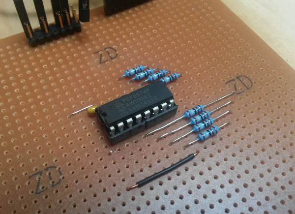
I usually forego the ubiquitous breadboard and go straight to a stripboard. Breadboards are great if you want to get something up and running quickly as a proof of concept. If you’re going to be using a thing for some time and it’s reasonably simple you can save yourself much head scratching and frustration if you take a little extra time up front and make a stripboard version. With this test jig I gave myself plenty of room so I can make changes later if I need to.
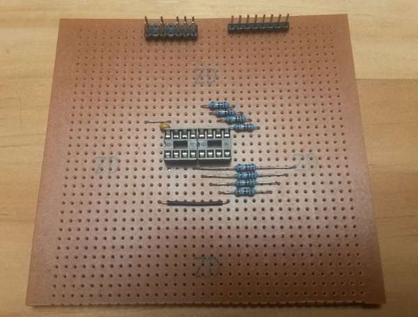
Test Jig Stripboard
I like to use an IC socket for initial stripboard designs. With an IC socket you can connect power to your board and measure voltages at the important pins to confirm it’s OK before connecting it to power with the IC installed. It’s a good idea to measure that your voltage rail has the correct voltage level and that it’s the right way around (don’t laugh, it happens). I also like to use double row headers for power and I2C connectors, this lets me daisy chain boards together.
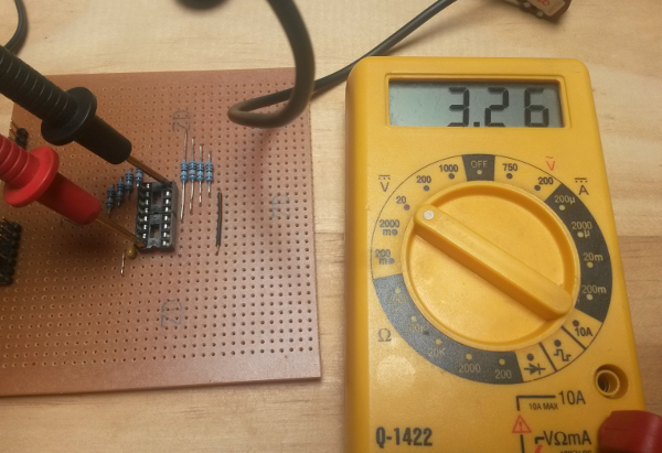
Test Jig Bringup, 3.3V between VCC and GND, all good.
Once the expansion board is constructed and electrically tested with the multimeter, it’s safe to plug in a pcf8574 and connect it to the Raspberry Pi.
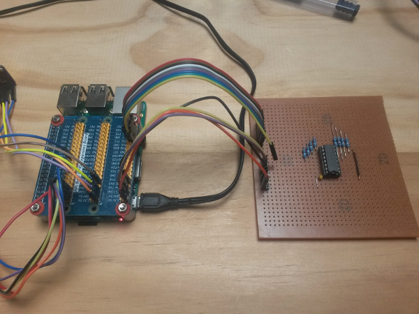
Everything connected and ready to test
The Software
The idea here is to write an Android Things application that uses the pcf8574 driver to exercise a real pcf8574, then read the Raspberry Pi GPIO pins to confirm that the pcf8574 IO pins are in the states that we expect.
What’s it supposed to do?
The pcf8574 is an I2C 8 bit IO port expander, this means that you can use it as an 8 pin output or input port, you can set its pins to be high or low, you can read what states the pins are, high or low. The pcf8574 driver is supposed to set port pin values directly by writing a byte to the port pin, it lets you set individual pit pins as high or low without affecting the other port pins. Here’s the interface that the pcf8574 driver implements:
/**
 * Interface for an 8 bit IO port see {@link nz.geek.android.things.drivers.i2c.Pcf8574} for implementation
 */
public interface IoPort {

  /**
   * write a 'byte' to the port. This takes an {@link int} the LSB of the int is used.
   * @param mask data does not affect port state when mask bit is 1
   * @param data the data to write to the port
   * @return true when the data is written successfully
   */
  boolean writeByte(int mask, int data);

  /**
   * Read the current state of the port. The LSB of the returned int will be
   * the value last written to the port.
   * @return
   */
  int readValue();

  /**
   * set the given port pin to the given value
   * @param pin the pin to set [0:7]
   * @param state true to set it, false to clear it
   */
  void setPin(int pin, boolean state);

  /**
   * Close the port. The port is invalid after being closed.
   */
  void close();
}
The driver uses a bitwise mask letting you set or clear some of the pins of the port without affecting the state of other pins. I have unit tests in the driver to confirm the mask works correctly and only the port pins are written to that should be. The unit tests confirm the Android Things I2C methods are called with the correct arguments. The test jig will confirm the arguments to those methods cause the real world to change as I expect.
The Android Things test application
The test application will be an Android Things app with my thing-drivers library added as a compile dependency. The application needs to access some Raspberry Pi GPIOs, the pcf8574, and give me some kind of indication that everything works OK. The target user is me, the driver developer, so I’m happy with logcat messages. If the target user was someone else, say a production worker in a factory testing pcf8574 expander boards I would need something more useful to them, maybe an LCD or a big green/red LED.
The application will connect to the pcf8574, open 8 Raspberry Pi GPIOs. It will then change the state of each of the pcf8574 pins and check that the Raspberry Pi GPIOs reflect the expected changes. This could be done as Instrumentation Tests in the Android Things project but I want to make a deploy-able application. The ultimate, slightly contrived, goal of the test jig is to be a production test jig in a factory making pcf8574 expansion boards. For that I’ll need the application on a device in the factory, with a nice UI that a factory worker would enjoy using.
In my application I create an array of Gpios that map to the pcf8574 IO pins. I specify the array mapping and which Raspberry Pi GPIOs I’m using.
  private static final String[] TEST_GPIO_NAMES = {"BCM21", "BCM26", "BCM20", "BCM19", "BCM16", "BCM13", "BCM12", "BCM6"};
  private Gpio[] gpioMap = new Gpio[8];
The array mapping means that I can access pcf8574 D0 as gpioMap[0], D1 as gpioMap[1] etc. I initialise the Raspberry Pi GPIOs as inputs, active high.
  private void initGpios() {
    Log.d(TAG, "initGpios: ");
    PeripheralManagerService manager = new PeripheralManagerService();

    for(int i = 0; i < gpioMap.length; i++) {
      try {
        Gpio gpio = manager.openGpio(TEST_GPIO_NAMES[i]);
        gpio.setDirection(Gpio.DIRECTION_IN);
        gpio.setActiveType(Gpio.ACTIVE_HIGH);
        gpioMap[i] = gpio;
      } catch (IOException e) {
        //
      }
    }
  }
The tests consist of setting the state of pcf8574 pins and confirming that the Raspberry Pi GPIOs change accordingly. I have a helper method to check the Raspberry Pi GPIOs against a given value.
  /**
   * Check that the current state of the Raspberry Pi GPIOs is
   * the same as the given expected value
   * @param expected the value expected on the GPIO pins
   */
  private void checkGpios(int expected) {
    for (int i = 0; i < gpioMap.length; i++) {
      if (gpioMap[i] != null) {
        try {
          boolean actualPinValue =  gpioMap[i].getValue();
          boolean expectedPinValue = (((1 << i) & expected) == (1 << i));
          Log.d(TAG, "checkGpios: Pin: " + i + (actualPinValue ? " HIGH " : " LOW  ") + ((actualPinValue == expectedPinValue) ? " OK" : " FAIL"));
        } catch (IOException e) {
          //
        }
      }
    }
  }
Then it’s just a matter of setting pcf8574 pins and seeing if they are set correctly.
  private void runTest() {
    Log.d(TAG, "runTest: ");
    testValue(0x00);
    testValue(0x01);
    testValue(0x02);
    testValue(0x04);
    testValue(0x08);
    testValue(0x10);
    testValue(0x20);
    testValue(0x40);
    testValue(0x80);
    testSetPin();
    testClearPin();
  }
The testValue() method uses the writeByte() method of the interface.
  private void testValue(int value) {
    Log.d(TAG, String.format(Locale.UK, "testValue: 0x%02X", value));
    pcf8574.writeByte(0x00, value);
    checkGpios(value);
  }
The testSetPin(), and testClearPin() methods use the setPin() method of the interface.
  private void testSetPin() {
    Log.d(TAG, "testSetPin: ");
    pcf8574.writeByte(0x00, 0x00);
    pcf8574.setPin(0, true);
    checkGpios(0x01);
    pcf8574.setPin(1, true);
    checkGpios(0x03);
    pcf8574.setPin(2, true);
    checkGpios(0x07);
    pcf8574.setPin(3, true);
    checkGpios(0x0F);
    pcf8574.setPin(4, true);
    checkGpios(0x1F);
    pcf8574.setPin(5, true);
    checkGpios(0x3F);
    pcf8574.setPin(6, true);
    checkGpios(0x7F);
    pcf8574.setPin(7, true);
    checkGpios(0xFF);
  }

  private void testClearPin() {
    Log.d(TAG, "testClearPin: ");
    pcf8574.writeByte(0x00, 0xFF);
    pcf8574.setPin(0, false);
    checkGpios(0xFE);
    pcf8574.setPin(1, false);
    checkGpios(0xFC);
    pcf8574.setPin(2, false);
    checkGpios(0xF8);
    pcf8574.setPin(3, false);
    checkGpios(0xF0);
    pcf8574.setPin(4, false);
    checkGpios(0xE0);
    pcf8574.setPin(5, false);
    checkGpios(0xC0);
    pcf8574.setPin(6, false);
    checkGpios(0x80);
    pcf8574.setPin(7, false);
    checkGpios(0x00);
  }
That’s it. Driver verified on actual hardware. Tests pass. Ship it!
Next steps
With everything set up I can now use the test jig for something useful, i.e., to extend the driver and implement a new feature from the product backlog. You may have noticed that in the interface there’s no readPin() method. There is a readValue() method that claims to return the last value written to the port, but nothing that reads the pin value. That’s because there’s something about the pcf8574 that I don’t really understand. The data sheet calls the IO port pins ‘quasi-bidirectional.’ I think this means that they can be inputs and/or outputs. I don’t know what happens when you set a pin as high or low, then try to read it. Does it return the value that you wrote, or does it return the value the pin is biased at. If you write a 0 to make it low it drives the output pin low, but if there’s an external pull up resistor on the pin, what happens when you read it? does it return 0, the value you wrote, or 1, the value set by the pull up? Now that I have the test jig, and a test application I can experiment with this and hopefully be able to add a readPin() method to the driver. I’ll cover this driver extension work in a future post.
Conclusion
In this experiment I have created a hardware test jig to help me verify the operation of my Android Things driver for the pcf8574. I can now use the test jig to implement new features, and verify the current features. Test jigs make it easy to verify correct operation of a device driver, simplify driver development and help you to automate much of your production validation.