Making things do stuff

Month: January 2017

Android Things Driver Testing

So you’ve written your first device driver for Android Things. You think it does what it’s supposed to. I mean, it seems to work. Hardware can be complicated. How can you be sure you’ve implemented your driver correctly? Are you sure you’ve understood the device’s data sheet? How do you test all of your driver features? How can you prove it’s working properly?

One thing you can do to verify your driver works correctly is to make a test jig. A test jig is a physical representation of the device your driver is written for. It may be an actual device or as close an approximation as you can find or make. The closer it is to the real thing the better.

Test jigs come in all shapes and sizes, and all levels of completeness. The test jig allows you to verify your driver on actual hardware. It can also make the development and testing of your library easier, saving you a lot of development time. Sparkfun have a tutorial on using pogopins to make test jigs. It’s well worth the time to read if you want to see production testing in action.
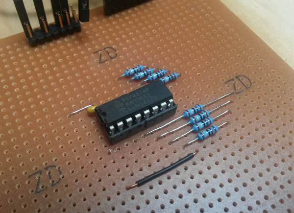
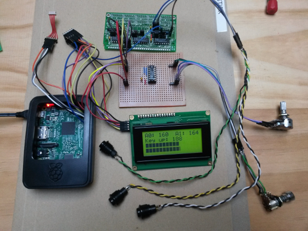
 

PCF8574 Test Jig

Making a driver test jig

I’m going to make a test jig for my pcf8574 driver. I’ll use a Raspberry Pi with an expansion board containing a pcf8574. I’ll create a test application that uses the driver to exercise the hardware and I’ll use the Raspberry Pi’s GPIO pins to confirm the driver does what I think it does. The concepts are the same as those described in the Sparkfun article, but I won’t go as far as making a dedicated PCB. The test jig is part of a two pronged strategy to device driver testing: unit tests verify that the logic of my driver is correct, and the test jig verifies that my driver manipulates the physical world as expected.

Continue reading

Hardware or Software?

Picture this. You’ve seen a thing on the Internet. Someone has made something. It’s cool. There’s a fritzing diagram and the source code on github. You want to make the thing yourself. You collect the parts needed to reproduce the thing. You study the diagram. You hook everything up carefully. You run the software, and, and, nothing. It doesn’t work. Why, dammit, why?

Before you turn to StackOverflow, or submit a bug report, you need to collect information about the problem you’re having. But how? Where do you start? What can you do?

Continue reading

What colour is that Android Thing?

In this experiment I will connect a colour sensor to Android Things. The Colour sensor is a TCS34725, a red, green, blue and clear light sensing light-to-digital converter. I’ll connect the sensor to a Raspberry Pi 3 running Android Things preview image 1 and display the sensor readings on a Character LCD display.


The TCS34725 module and LCD display

Continue reading

I need more UARTS Android Things


UPDATE: 12 March 2017

Android things developer preview 3 adds support for USB-serial devices, making this method redundant for single USB-Serial adapters. This may be still useful for the QUAD UART used in this post. Read more about it here.


There’s nothing quite like the good old fashioned UART for connecting things together. It’s a technology that persists because it’s simple and it works. The Raspberry Pi has one UART. With it you can connect to exactly one peripheral. That’s not enough. We need more UARTs.

One solution to the ‘not enough UART’ problem is to use a USB-Serial converter. There’s been a Linux kernel driver for the FTDI USB-serial converters for years now, these are a well supported, mature technology. The aim of this experiment is to see if I can get an FTDI USB-Serial converter working with the Raspberry Pi 3 running the Android Things preview image 1.

4 port FTDI UART

Continue reading

Adding Buttons to Android Things

In this experiment I’m going to add buttons to Android Things using the user space input driver extension mechanism provided by the platform. I’ll be using momentary push buttons connected to a Raspberry Pi running the Android Things preview image. The buttons will be connected via an I2C IO port, the PCF8574. I’ll use one GPIO on the Raspberry Pi as an ‘interrupt’ line to detect a button press, then I’ll read the button states and report button presses to the framework as input events.

The setup with buttons

Continue reading

Measuring analog values with Android Things

Sometimes you need to read analog sensors in your IoT project. The values could be from light sensors, potentiometers, or other things that aren’t cool enough to get digital equivalents. The Raspberry Pi doesn’t have an Analog to Digital Converter (ADC) so you need to add one if you want to use analog sensors. In this experiment I’m going to add an ADC to the Raspberry Pi and use it from an Android Things project to measure analog values. The ADC I’ll use is the four channel, 8 bit PCF8591.

The Android Things PeripheralManager may get analog pins in future but for now it doesn’t, so I’m going to add the PCF8591 to the things-drivers library.

Two ADC channels

Hardware

  • Raspberry Pi 3 running Android Things preview image.
  • A PCF8591 on a breadboard or module like this.
  • A display of some kind (I’m using an LCM1602 and character LCD).
  • your trusty level shifter for connecting 3.3V Raspberry Pi I2C to 5V peripherals.
  • something to measure (I’m using potentiometers).

Continue reading

© 2025 android.geek.nz

Theme by Anders NorenUp ↑