In this experiment I will demonstrate how to use an external MCU to manage tricky time-constrained tasks on behalf of Android Things. Using an ATTiny85 microcontroller I’ll interface a Dallas 1-wire temperature sensor, the ubiquitous DS18B20, to a Raspberry Pi running Android Things.
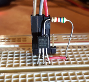
The DS18B20 temperature sensor
Background (why)
Since the introduction of Android Things some have questioned the limits of Android Thing’s GPIOs. Collecting data from the Raspberry Pi running Raspbian or similar will show that GPIOs on Android Things are too slow for some applications. Discussions about GPIO speed highlight a point about operating systems in general and Android Things in particular. Android Things is not a real time OS. It will miss deadlines. It will not respond to interrupts predictably enough to satisfy some of the tasks that people may be expecting it to perform. The problem here is not the OS, but the expectations.
As mentioned in this SO answer one possible solution to this problem is to have an external helper MCU handle the hard real-time stuff. Great, but what is all this real-time stuff about?
Real-time != fast
I use the definition of a real-time system I heard in a LinuxLink Radio podcast by Timesys. As discussed in the first few minutes of this episode: real-time does not mean fast, it means predictable. You can, (and usually do), have a fast real-time system, but it’s not the speed that makes it real-time, it’s the system’s predictability.
Do we need ‘real-time’
Given the ‘predictable’ definition of real-time given above we probably don’t need a real-time system for peripheral integration with Android Things, just a fast one. We won’t satisfy our ‘predictable’ definition of real-time, but we can be fast enough that it doesn’t matter. Of course, if it’s too much faster than it needs to be we’re wasting power. We should slow it down and save energy.
Hello hardware pattern
To solve the problem of Android Things not being responsive, or predictable, enough to handle tight timing constraints we can ‘invent’ a hardware pattern. I say invent in inverted commas because it’s not really a new or novel solution to the problem. Also, I don’t think that ‘hardware patterns’ are really as much of a thing as software patterns.
I don’t hear many hardware people talk about ‘patterns’ in hardware design, but I’ve seen them used. A pattern is an accepted solution to a particular problem, they’re common in software and promote the reuse of software components. I haven’t seen the same adoption of the concept in hardware design, but I often see hardware designs and schematics that look familiar. Hardware engineers build up a toolbox of solutions to common problems like software engineers do, but I don’t see as many arguments about them as I do about software patterns, but then I don’t hang out on hardware engineer forums so I can’t judge.
The facade adapter fandango
In this pattern, we’re offloading some part of the system to an external component so that we don’t have to worry about strict timing and deadlines. It’s like an adaptor in that it’s adapting I2C (which we can do and are used to in Android Things) to 1-wire (which we can’t do as easily in Android Things and since 1-wire has some strict timing constraints we may not be able to do reliably). It’s also a facade in that it hides something we don’t want to deal with and presents an interface that we can handle. We’re simplifying the interface to “what’s the temperature?” This is why we’re doing it this way an not using a bus master. Those things are very general purpose. We want to simplify the 1-wire interface. Maybe it’s more of a fandango?
I’ll tackle this project in a few stages:
- MCU Selection
- toolchain setup
- I2C slave on MCU
- DS18b20 on MCU
- Android Things code
Step 1 – MCU Selection
The selection criteria for this is simple: what do I have in my draw of miscellaneous boards? What was I tempted into buying one evening from Aliexpress. Top of that list for me is a digispark clone. An Attiny85 board, programmed with a micronucleus bootloader. You could probably use something like the Adafruit Trinket.
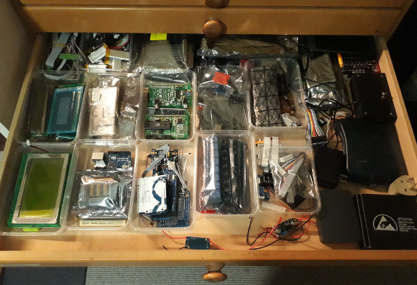
The magic drawer of late night purchases
In the real world I have observed much more comprehensive selection criteria specifying minimum system requirements, cost, power budget, regulatory compliance, and a whole host of other factors. I’ve seen spreadsheets drawn up, datasheets studied, and meetings had, criteria argued, and decisions made. I’ve also seen times when the MCU used on the last project was “close enough.”
The ATTiny85 is probably the smallest I could get away with for this project without having to hand craft bit-banged I2C and 1-wire in assembler. It has silicon support for I2C and there are open source libraries available for I2C and 1-wire that will most likely work on it.
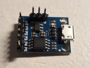
The “Digispark”
Having selected the MCU we can finalise the system architecture.
System architecture
The system architecture consists of a Raspberry Pi running Android Things, the ATTiny85 board connected to a DS18B20. I’m using a level shifter on the I2C lines between the Raspberry Pi and the ATTiny85. The level shifter is required because the ATTiny85 board runs at 5V (probably because of the USB connection on the board). The USB connection on the board is required for programming. I’ll keep the board at 5V so that I don’t fry anything absent mindedly. Both the ATTiny85 and the DS18B20 will operate at 3.3V so after the development work is complete I could save some BOM cost by removing the level shifter and connecting the ATTiny and DS18B20 supplies to 3.3V (As long as I’m careful not to connect the ATTiny85 board to USB afterwards, or smoke may escape).
Below is a simplified circuit with the ATTiny85 on breadboard without any of the USB components that are on the digispark.
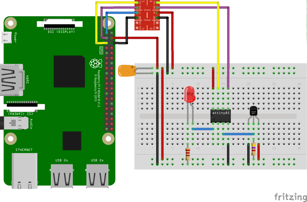
Simplified schematic without USB components
Step 2 – Toolchain setup
I’m going to use PlatformIO to write software for, and program, the ATTiny85. Platformio is somewhat of a new kid on the block and I’ve never really enjoyed the Arduino IDE. We can use this project to try it out. Go to the PlatformIO website and follow the instructions to get started. The setup consists of installing Atom, then installing PlatformIO. It’s too easy.
I’ve created a PlatformIO project here you can import into PlatformIO. Just clone the project and then in PlatformIO select “PlatformIO -> Open project folder…” and select the project you’ve just cloned.
What I like about PlatformIO is the platformio.ini. This simple file lets you specify what libraries you want to use and PlatformIO automagically downloads them for you. You don’t have to mess around installing anything. Just search on the libraries site and add the reference to your ini file.
Using PlatformIO I can mash away at the keyboard until some ‘C’ like source code comes out, then I can upload it to the digispark from the IDE. Magic.
Step 3 – I2C slave on the MCU
I’m using the TinyWireSio library to provide the I2C functionality. This lets me turn the ATTiny85 into an I2C slave so that the Raspberry Pi (as the master) can request temperature readings. The ATTiny responds with the latest temperature reading.
Step 4 – 1-wire on the MCU
I started out using the OneWire and DallasTemperature libraries to communicate with the DS18B20. For reasons still unknown to me I couldn’t get the DS18B20 to work on the pins of the ATTiny that I tried. In the course of trying to figure out why it wasn’t working I turned to my own DS18B20 library that I’d developed some years ago when my car’s temperature gauge broke and I decided to make my own. That was waaaay back in 2004. I remember bashing my head against the 1-wire search ROM algorithm in the 1-wire datasheet for a few days to figure it out. It seams a shame to waste that effort so I’ve resurrected that code for this project. It turned out that my code didn’t work on the selected pin of the ATTiny either. It works OK on one of the pins that I didn’t want to use, one that’s also used by micronucleus. I assume that OneWire and DallasTemperature would work on that pin too (PB4). The rest of my old native AVR library is here if you want to check out what life was like before Arduino.
ATTiny85 Code
Using the Arduino setup-loop paradigm I use the setup function to set the LED pin as an output. Then I initialise the 1-wire bus, which searches the bus for devices. After this I initialise the TinyWire library and give it a handle to the function I want called when an I2C read is received by the Attiny85.
void setup() {
  pinMode(LED_PIN, OUTPUT);
  num_devices = ds18b20_init();
  TinyWireS.begin(I2C_SLAVE_ADDRESS);
  TinyWireS.onRequest(requestEvent);
}
I’ve defined the I2C slave address as 0x66
#define I2C_SLAVE_ADDRESS (0x66)
The function called on an I2C read replies to the I2C master with the latest temperature.
void requestEvent()
{
    TinyWireS.send(temperature);
}
The loop continually reads the temperature from the DS18B20 and checks for activity on the I2C bus. I’m also toggling an LED if a temperature sensor is connected. If no sensor is connected the LED will stay on.
void loop()
{
  TinyWireS_stop_check();
  digitalWrite(LED_PIN, HIGH);
  tws_delay(DELAY_TIME_MS);
  if (num_devices == 0) {
    num_devices = ds18b20_init();
  }
  if (num_devices > 0) {
    digitalWrite(LED_PIN, LOW);
    tws_delay(DELAY_TIME_MS);
    temperature = ds18b20_read_temp(0);
  }
}
Step 5 – Android Things code
On the Android Things side now all I need to do is read the I2C device at address 0x66 and I’ll get the temperature back (in Celsius). I created a BusBuddy class that extends a BaseI2cDevice from my things-drivers library (enjoying the chunky bits of my own dog food).
public class BusBuddy extends BaseI2cDevice {

  /* package */ BusBuddy(I2cDevice device) {
    super(device);
  }

  public static BusBuddy create(int address) {
    return new BusBuddy(getDevice(getBus(), address));
  }

  public void destroy() {
    super.close();
  }

  public int readByte() {
    if (device == null) return 0;

    byte[] buffer = new byte[]{0};

    try {
      device.read(buffer, 1);
    } catch (IOException e) {
      // ignore
    }
    return buffer[0];
  }
}
In my main activity I pass the I2C address of the ATTiny85 to the create method and periodically read the temperature
public class MainActivity extends Activity {
  private static final String TAG = MainActivity.class.getSimpleName();
  Handler handler = new Handler();
  Runnable updateTemperatureRunner = new UpdateTemperatureRunner();
  private BusBuddy busBuddy;

  @Override
  protected void onCreate(Bundle savedInstanceState) {
    super.onCreate(savedInstanceState);
    busBuddy = BusBuddy.create(0x66);
    handler.post(updateTemperatureRunner);
  }

  @Override
  public void onDestroy() {
    super.onDestroy();
    handler.removeCallbacks(updateTemperatureRunner);
    if (busBuddy != null) {
      busBuddy.destroy();
    }
  }

  /**
   * runner to periodically read temperature
   */
  private class UpdateTemperatureRunner implements Runnable {

    @Override
    public void run() {
      Log.d(TAG, "The temperature is: " + busBuddy.readByte() + "\u00b0C");
      handler.postDelayed(this, 1000);
    }
  }
}
The result is the temperature displayed in logcat. The next step would be to do something useful with temperature. Display it, upload it somewhere, disco
D/MainActivity: The temperature is: 21°C
D/MainActivity: The temperature is: 21°C
D/MainActivity: The temperature is: 21°C
D/MainActivity: The temperature is: 21°C
D/MainActivity: The temperature is: 21°C
What did I learn?
In this project I learnt a bit about PlatformIO. To me it seems better than the Arduino IDE. I’m used to ‘proper’ IDEs like Android Studio. I’ve always found the Arduino IDE to be a bit basic, lacking in essential features.
I learnt that the ATTiny85 pins are not all created equal. This is something I can look into for future projects.
Was this a realistic project? Maybe. There are other temperature sensors I could have used that wouldn’t require the use of 1-wire. I didn’t have any in my parts drawer so the DS18B20 was an easy choice. This also demonstrates a framework for offloading work that you don’t want to do, or don’t think you can do reliably with Android Things. It makes me wonder what else I could offload to an external MCU, and what other ways could I connect them to Android Things.
What was the hardest part? I couldn’t find a fritzing part for the digispark, which made making a nice circuit diagram difficult. Making a part looked “too hard basket” for this project but I’ve added “making fritzing parts” to my personal backlog.