In this post I will demonstrate how to use an LED matrix display with Android Things. I want to use an LED matrix display for my bus stop sign project. I have been using a character LCD which doesn’t give much visual impact. LED matrix displays are big and bright and can be seen clearly from a greater distance than character LCD displays.
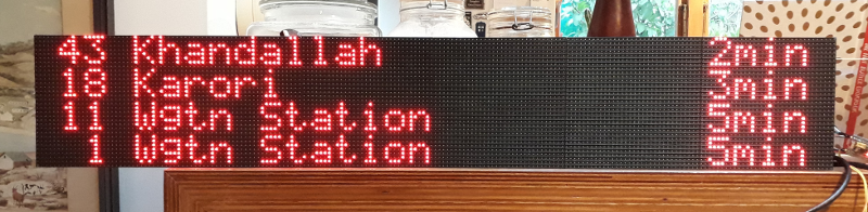
That’s better
Hardware
The hardware for this project consists of:
- An Android Things development board
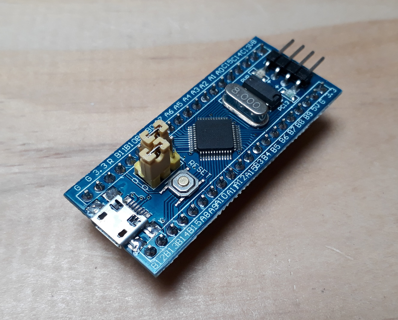
- an stm32 development board (Blue Pill)
- 3 32×64 LED dot matrix boards daisy chained together
- a 5V power supply
Problems to solve
There are two problems to solve. I need to:
- drive the LED matrix display (the display has no smarts).
- control the display from Android Things.
The Android Things board
I’m using a Pico i.MX6UL board for this project. It’s running version 0.5.1 of Android Things. I have fitted a GPIO adapter plate to my Pico Pi as it makes connecting peripherals easier (it has handy pin labels too).

PICO-PI i.MX6UL
The LED matrix display
LED matrix displays are available from your favourite cheap-crap-from-China website. It seems like a few ‘standard’ interfaces have emerged, none of which are particularly well documented. The display modules I ordered claim to use the ‘HUB08’ standard. I went for a one colour module to get started, because they are cheaper and simpler. If it works out then I’ll try the three colour modules. The modules can be purchased with a controller, but there was little information about the controllers too. I had no way of knowing if an off the shelf controller would do what I want so I decided to make my own.
Official information about LED matrix displays is hard to come by. Luckily, there are lots of people who have worked out how to use them. I built on their work to make a controller that I could use from Android Things. I found this post on the stm32duino forum claiming some success with a HUB08 display using a library from Seeed Studio, so I based my controller on that work.
The data is shifted in to the display and latched in place. Most displays I’ve seen are a multiple of 8 x 8. I’m used to my LCD display being 4 rows and 40 columns of characters. LCD displays use a 5×7 font, so to have 4 rows on an LED matrix display I would need to get one that’s 32 LEDs high. This is 7 ‘pixels’ for each row plus 1 pixel between rows. I did my usual cheapskate move of searching on AliExpress and sorting by price and ended up getting 3 of these 32 x 64 modules. This would give me a 32 character width.
My display modules were dropped in transit, so it had a few LEDs missing. Not great packaging, but it was only a few corner LEDs, not a show stopper.
An LED matrix controller
I need a way to generate the signals required to drive the display. This is something I don’t want to do with Android Things. The display needs to be continuously updated by the controller. If the controller stops updating the display, only one row of LEDs will be lit. Android things is not the right tool for the job. Android Things has many more important things to do, and wont be able to update the display fast enough. I’ll use hardware dedicated to the job.
I chose to use an stm32 development board. The advantage of the stm32 is that it’s fast, it should be fast enough to drive the display without much flicker. The selection criteria was straight forward, and transparent, no kick backs from board vendors were necessary in the selection process. I chose the closest ‘fast enough’ processor I had in my drawer of bits.
Having a dedicated display controller means that I can solve, or at least hide, another issue with Android Things, boot speed. It takes a long time for Android Things to boot. From the time power is applied to the time the display is first updated can be a few minutes, which is too long. The problem is not really that it takes a long time to boot, the problem is the device doesn’t appear to be doing anything. No user is going to plug a device in and wait a minute without any indication that the device is on, they’ll intervene long before the minute is up, assuming that the ‘damn thing’s broken.’ The stm32 takes no time at all to start controlling the display, so I can have it write messages to the display until the bus stop code on Android Things is up and running.
The display controller
Compromises – the division of labour
So far, my system looks like this; I have a device running Android Things, a device running control firmware for a display, and the display itself. I need a way to connect the pieces of the system together and define how they will communicate.
The interface between the display and display controller is already defined, there’s not much to do here. The interface between the controller and Android Things is not defined, it’s up to me to decide. Realistically my options limited to busses that Android Things supports. At the time of writing this is UART, SPI and I2C. The UART is probably the simplest, I’d just need to define a set of commands and send them to the controller. Many people are familiar with UARTs as the good old fashioned ‘Serial Port.’ It’s been my experience that UARTs, though simple and reliable, are in demand. You usually want one to connect as a debugging tool, so it’s good to reserve one for that. When the number of available UARTs is limited, and if their function is shared by other parts of the system, it’s better to choose something else. SPI is ‘faster’ than I2C, so I’m going to use SPI.
SPI
Serial Peripheral Interface (SPI) is one of the industry standard embedded busses supported by Android Things. You can access devices on an SPI bus from java. Sparkfun have a good introduction to the interface standard if you are interested in a deep dive. For our purposes it’s good enough to know that it’s a way to connect something you want to control by an Android Things device with a few wires. SPI is a master-slave system whereby one device controls communication to one (or more) slave devices.
The stm32 would be an SPI slave, with Android Things its master. I need to connect the 4 SPI lines between the two, I also need to connect 3.3V and GND between the two. The Android Things board will be supplying power to the stm32.
Wiring it up
With the decisions about how to communicate between Android Things and the display controller made I can wire it up. Here’s how I connected everything together. This diagram shows the connections for a Raspberry Pi. If you’re using the Pico-Pi with an i.MX6UL it has MOSI and MISO swapped. The connector block on the right hand side of the diagram represents the LED Matrix display.
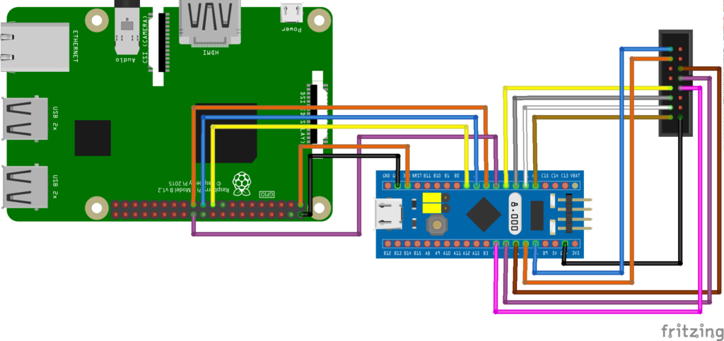
The Fritzing diagram looks a little cleaner than the actual device. I’ve got some Pi HAT prototype boards coming to clean it up a bit. I’ll probably end up making a custom HAT with the stm32 and some connectors for LED matrix displays. But for now it looks like this:
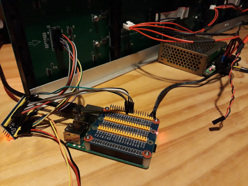
Spaghetti
Defining a protocol – graphical or character
SPI is a way to get bytes between devices. What those bytes actually mean is up to the device designer to define. I’m going to define a simple protocol that specifies how I communicate between my application on the Android Things board and my LED matrix display controller. Since I’ve defined ‘characters’ in the controller I’m going to extend that abstraction to the interface. I could, just as correctly, define a pixel based interface. A pixel based interface would have been better for a graphical interface, if I needed to draw pictures on the display, but I just want to write text, so I’m keeping it simple.
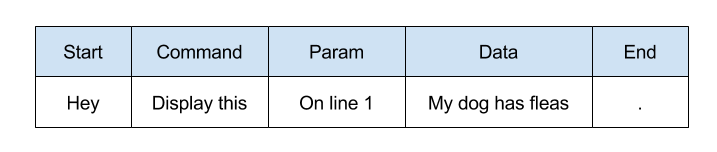
A protocol is simply the language that two things understand so they can communicate. My display doesn’t say much, it just listens. The protocol simply has to cover “Hey, display this on line one, ‘My dog has flees’.” or “Hey, turn on.” or “Hey, turn off.” Looking at those sentences you could break them up in to a few segments; there’s the “Hey” which is a way of starting communication, then there’s a command; “display this” or “turn on,” there’s a parameter which is extra information pertaining to the command “on line 1,” then there’s a “.” which means “that’s the end of the command.” Some commands have extra data, like “My dog has flees” which is the text that I want to display.
I could use “Hey” to start my commands but that has two problems. Firstly it’s three characters, that’s a waste of time and space. Secondly it uses characters that I want to display. What if I want to display “Hey” my controller could get confused, or I’d need extra logic to escape commands from things I want to display. The solution to both those problems is to use data that is outside of the character set that I want to display. I also need a way to represent text as bytes to be transported to my display controller over SPI. Lucky for me, there’s a well established way to encode text as bytes, ASCII. ASCII defines 32 control characters that I can use to implement the commands I need, without using ‘printable’ characters.
Most proper protocols have a header, a body, and some kind of footer (usually containing a checksum). My protocol is light weight so the header will consist of a start byte, command and sometimes a parameter.
My display protocol
Here are my display protocol commands, I defined a few extra control commands to turn the display on and off, and clear lines. Some commands have parameters, others do not.
  // display commands (reusing ascii command characters)
  private static final byte CMD_PRINT_LINE = 0x04;
  private static final byte CMD_CLEAR_LINE = 0x05;
  private static final byte CMD_CLEAR_DISP = 0x06;
  private static final byte CMD_SET_CHARACTER = 0x07;
  private static final byte CMD_DISPLAY_ON = 0x08;
  private static final byte CMD_DISPLAY_OFF = 0x09;
The idea behind making my LED display a character display is that from Android Things I only need to deal with characters and not pixels. Since each character is made of 30 pixels (6×8 including the 1 pixel space between characters) I’m doing 30 times less work this way. From Android Things I want to just use the simple protocol and not worry about the implementation details. Here is the full list of commands and parameters for my display protocol:
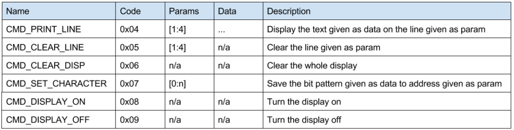
The full command set
Android Things code
I have a driver for character LCD displays in my things-drivers library. The driver implements an Lcd interface that I had already defined. This was with a view to having different methods of connecting a character LCD display. I had implemented an I2C connected display, and left the way open to implementing a display that could be connected with GPIOs. The LED display uses very similar concepts. It has a width and height in characters, lines, a font map, the ability to define custom characters, and a few commands like display on and off. I reused these concepts in the character LED display. I refactored the Lcd interface to make it CharacterDisplay. Then I implemented that interface in my LedCharacterDisplay. Now I can swap out the LCD display for an LED display and I don’t have to significantly change my existing bus stop sign code. I generalised the LCD specific bits by renaming setCgRam to setCustomCharacter. The diff for the interface change is here if you want to check it out. The refactored interface is shown below.
/**
 * Interface for a character display
 */
public interface CharacterDisplay {
  /**
   * Connect to the display. This initialises the display.
   */
  void connect();

  /**
   * Disconnect from the display
   */
  void disconnect();

  /**
   * Enable the display
   * @param enable true to enable, false to disable
   */
  void enable(boolean enable);

  /**
   * Print a message to the display starting at the given display line
   * @param line  the line to print the message [1:height]
   * @param message the message to print
   */
  void print(int line, String message);

  /**
   * Clear a given line of the display
   * @param line line to clear [1:height]
   */
  void clearLine(int line);

  /**
   * clear the display. Fills DDRAM with space character (0x20)
   */
  void clearDisplay();

  /**
   * Switch on and off the backlight
   * @param enable true to enable
   */
  void enableBackLight(boolean enable);

  /**
   * Does the display have a back light?
   * @return true if it does
   */
  boolean hasBackLight();

  /**
   * Get the number of display character rows
   * @return rows
   */
  int getWidth();

  /**
   * Get the number of display character columns
   * @return columns
   */
  int getHeight();

  /**
   *
   * write a bit pattern for a custom character to the display. What the
   * bit pattern means depends on the display, for an LCD display the
   * bit pattern is defined as:
   *
   * <pre>
   * bit pattern     eg          hex
   * 76543210
   * ---XXXXX        XXXX        1E
   * ---XXXXX        X   X       11
   * ---XXXXX        X   X       11
   * ---XXXXX        XXXX        1E
   * ---XXXXX        X   X       11
   * ---XXXXX        X   X       11
   * ---XXXXX        XXXX        1E
   * </pre>
   * @param address the 'address' to write the bit pattern to.
   * @param pattern the bit pattern to write
   */
  void setCustomCharacter(int address, byte[] pattern);

  /**
   * Variant of {@link #setCustomCharacter(int, byte[])} that returns the address used
   * to store the custom character
   * @param pattern bit pattern of the custom character
   * @return the address used
   */
  int setCustomCharacter(byte[] pattern);

  /**
   * initialise custom characters for the display of bar graphs
   */
  void initBarGraph();

}
The end result
Now my bus stop sign shows departures from a local stop on an LED matrix display. I put paper over the display as a diffuser, which softens it up a bit.
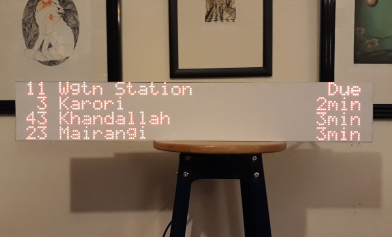
I call this piece ‘Stool with sign’
Next steps
I want to make a Pi HAT to put the stm32 and connectors on. At this stage I’m only planning on making it a character display, but turning it in to a graphical display is only a little firmware work. I’m going to get some RGB display modules and see if I can drive those before laying out the Pi HAT.
Resources