So you’ve written your first device driver for Android Things. You think it does what it’s supposed to. I mean, it seems to work. Hardware can be complicated. How can you be sure you’ve implemented your driver correctly? Are you sure you’ve understood the device’s data sheet? How do you test all of your driver features? How can you prove it’s working properly?
One thing you can do to verify your driver works correctly is to make a test jig. A test jig is a physical representation of the device your driver is written for. It may be an actual device or as close an approximation as you can find or make. The closer it is to the real thing the better.
Test jigs come in all shapes and sizes, and all levels of completeness. The test jig allows you to verify your driver on actual hardware. It can also make the development and testing of your library easier, saving you a lot of development time. Sparkfun have a tutorial on using pogopins to make test jigs. It’s well worth the time to read if you want to see production testing in action.

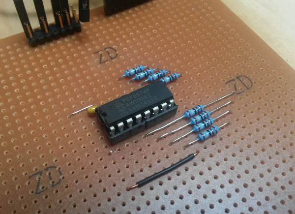
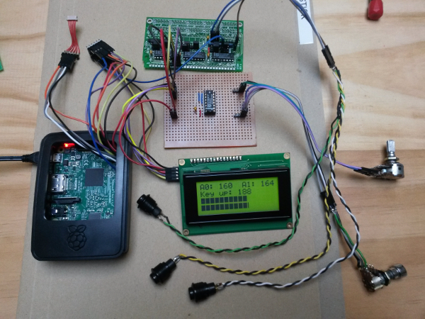
PCF8574 Test Jig
Making a driver test jig
I’m going to make a test jig for my pcf8574 driver. I’ll use a Raspberry Pi with an expansion board containing a pcf8574. I’ll create a test application that uses the driver to exercise the hardware and I’ll use the Raspberry Pi’s GPIO pins to confirm the driver does what I think it does. The concepts are the same as those described in the Sparkfun article, but I won’t go as far as making a dedicated PCB. The test jig is part of a two pronged strategy to device driver testing: unit tests verify that the logic of my driver is correct, and the test jig verifies that my driver manipulates the physical world as expected.
Continue reading


